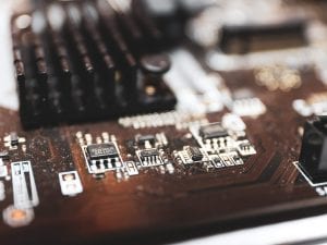
We continue to put electronic devices in testing environments that can affect the printed circuit board in their hardware. This could cause a range of issues in the PCB. For instance, a constantly moving device will carry a lot of pressure to the PCB and cause vibration failure. If electronics manufacturers don’t get serious about this aspect of their board design, their product will end up paying the price. Eventually, the PCB will fall apart, and the device will stop functioning. It’s, therefore, crucial to understand the causes behind high vibrations and methods of rectifying them in PCBs.

(Pixabay / ArtificialOG)
There are many industrial sectors where products are put in high-vibration environments. For example:
- Transport (aerospace, railways, autos, vehicles)
- Household devices and appliances (washing machine, juicer, blender)
- Agriculture (tractors, mills, combines)
- Power equipment (generator, welders)
- Military devices and transport
Typical failures in PCBs due to such high vibration environments include:
- Cracked capacitors
- Broken board traces
- Cracked joints
- Delamination of PCB
- Electric shocks
- Barrel-to-pad disconnect
- Through-hole cracking of pin lead
- Lead wire fatigue
These failures can greatly reduce the life and functionality of any device and lead to intermittent signaling. When energy brought into the product resonates on a high frequency, it causes heavy displacements. The key to saving your device lies in identifying these resonating frequencies, even if present at the lowest levels. Next, you increase the frequency by adding stiffeners.
How to Find Hidden Resonances?
Shake tables are used to find out the hidden resonance in a device. These tables use a Sine vibration pattern to identify the resonance. Testers watch a product on the shake table and vary the vibration frequency to figure out resonances. High Q mechanical resonances are difficult and come into play on a very small range of frequencies. For this, you must set the shake table to a random configuration to look for hidden resonance. This test is difficult and time-consuming.
Identifying all the frequencies on a shake table poses an even bigger challenge. First, it’s not always easy to see what’s going on and how all parts are affected. And if you do get close enough to get a better view, you expose yourself to moving pieces and parts—not just from the devices being tested but from the table hardware that holds things in place. Due to the stated difficulties, people are shifting to modal analysis to find out vibration frequency. Modal analysis is a technical test that is part of various CAD packages.
Other Considerations for Countering High Vibration Effects
Rubber
The most common cause of high vibration is the shock a device faces when dropped from a height. The impact of the drop contains all the high frequencies to damage the components. This particular impulse is easy to dampen with the help of a rubber bumper. Rubber bumpers with the correct customization provide smoother deceleration compared to no bumper. The material facilitates clever designs that are up to the challenge and take the product configurations into account. For example, you can change the cross-section of a rubber foot to achieve any level of frequency cancellation. The key is to work with an alignment that decreases the chances of larger displacements.
Plastic
Sine sweep tests on PCBs mounted on a plastic spacer yield interesting results. Spacers under the PCB are tested under a frequency range from 20-500 Hz at a constant acceleration of 1G. The test results in picking up a resonant frequency of 46 Hz, which is harmful to the product. Basically, it causes maximum PCB deflection and puts a lot of stress on the component’s lead wires. The outcome is a reduced lifespan and failure of the package. The resonant frequencies might come out similar for both rubber and plastic spacers in initial modes, but at a certain point, they will start to differentiate at higher modes. Displacement, peak acceleration level, and transmissibility ratio of PCBs are cut down to 28% in rubber spacers. So in comparison, PCBs are safer when mounted on a rubber spacer.
Keep in mind that your overall component’s weight and how the board is supported play a huge role in finding a connector that will pass all shock tests. Therefore, custom hybrid sizes and alignments can help make your device as secure as possible.
Potting
PCB potting involves encasing the whole electronics assembly, or a portion of it, in a potting compound. Special epoxies, silicone rubbers, or urethane are typical materials. The circuit board’s encapsulation helps secure the entire assembly from high vibration, shock, and other factors.
There are a few things to keep in mind when developing a potting solution for your board. First, it’s important to carefully choose the glass transition temperature and the durometer of the board. The potting material should neither be too soft or too stiff for the best results. Secondly, take into account the geometry when designing for thermal expansion. A mold design is ideal if you’re going to constrain the board in an enclosure. Lastly, make sure whatever materials you’re considering using are compatible with all the components they’ll come in contact with. Any incompatibility would eliminate the benefits of potting.
Design for Reliability
Another step you can take to address vibration issues is to design for reliability (DFR). DFR helps validate the reliability of a printed circuit board during the design phase before the PCB is built. Why do this? Because the stress the board goes through during manufacturing is a leading contributor to vibration-related failures. Solder joints and component leads are both susceptible to shock and require good DFM practices to counter the negative effects.
Our PCBA manufacturer specialists can assist you in designing the correct footprint sizes and pads for your parts. They can also offer you design rules that enable you to meet relevant IPC standards.
Video

