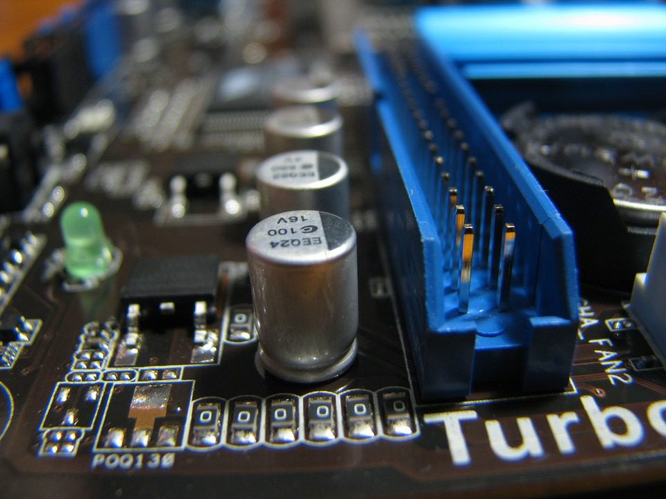
The power supply filter may seem like a minor part of a printed circuit board, but if it is designed incorrectly, you could end up with hardware that is unreliable or that fails. Unfortunately, this is more common than you might suspect. Problems with electronics can often be traced to shoddy design practices that generated defective power supply filters.

(Pixabay / LaurelRusswurm)
To ensure high-quality power supply filter designs, it’s critical to understand the requirements of the filter, use basic heuristics to detect component values, and replicate the design with the help of a circuit simulator.
One of the things that causes problems in PCBs is high-frequency ripple. This ripple occurs when power supplies switch or because of radio interference. The ripple passes through a linear regulator. If the ripple is too big, the regulator will stop working. The power supply filter can help augment the regulator so that it can handle greater power flow from unexpected ripples.
Inductor
In order to build a power supply filter, you need a single inductor and a damped capacitor. The rule of thumb for the inductance value for the filter is that it should be about 10 times bigger than all of the other inductances in the power supply succession.
Capacitor
As for the capacitor, you can change the inductor model schematic into a low-pass filter with the addition of a capacitor. You can experiment with low-ESR ceramic capacitors or tantalum capacitors. Watch the reaction of the supply ripple. Is it increasing or decreasing? Note that the frequency will have a small range and may be easy to overlook when you are conducting testing. Monitor the amount of drift as time and temperatures vary. If you are encountering resonance issues, you can try adding a series resistor.
Damping
To determine the optimal formula for damping, start with a circuit simulator. Pinpoint the first resonance. Then reconfigure the resistor value accordingly. You will find that the ceramic capacitor and resistor provide a design that is more easily replicated than that which you can achieve with a tantalum capacitor. This is owing to the fact that the tantalum capacitor provides a broader range of potential values for the ESR.
Load network
Next, you should simulate the load network, which can show you how a filter will act when placed on a circuit board. Make allowance for PCB trace inductance and bypass capacitors. You can draw up a model, but if you want a truer representation, you should use a Power Integrity Cad tool.
As you do your testing, you will likely note that the shape of the filter maintains its integrity when:
- The inductor is bigger than the total load produced by the smaller load inductor
- The damped capacitor is larger than the total of the bypass capacitors
Note that the simulated boards will not behave in testing exactly like they would in real life due to transmission line effects, but you can come close.
By-pass capacitors
You can use local bypass capacitors to store charges and lend current to high-frequency pulsating loads. You will need larger bypass capacitors to provide steady voltage. Closely examine each high-current pulsed load to see if you can detect signs of voltage ripple.
You may find that inductance can influence bypass capacitors in the power distribution network. To solve this problem, try damping the resonances at the power supply input filter. It doesn’t ensure a solution, but it can certainly assist.
In summary, you can ward off power distribution resonances with the aid of a well-designed, damped, low-pass filter by ensuring that it has a proper inductor and capacitor value in relation to the stray inductances and bypass capacitors respectively. You should also ensure damping resistance to mitigate problematic resonances.
