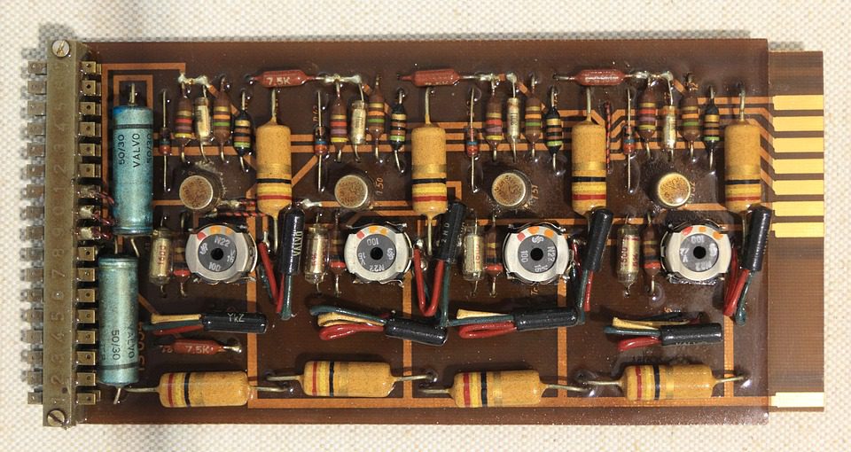
Designing printed circuit boards is no easy process. You have to develop your performance specifications. Then, you must find suitable components (which can require a lot of research). After that, you will need to simulate your design. Finally, you can send your design to a manufacturer such as EMS Solutions.

(Pixabay / olafpictures)
Unfortunately, there can be a lot of back-and-forth between your design team and your manufacturer that can bog things down. Sometimes, there are legitimate hang-ups, but often, there are small delays that could have been avoided with some basic quality control.
Before you submit your PCB design for production, here are a few things to double-check.
Files
As the standard image file format for PCBs, Gerber can provide the 2D binary images that effectively convey design, but errors are common in the loading process. Make sure to check your Gerber files with a viewer to ensure that they load properly and that the trace widths are good, the layers line up, etc.
Trace width and board outline specifications
Different manufacturers require different specifications for your board design. Some have established parameters for trace widths. Make sure that your trace spacing meets their minimum and maximum requirements. Other manufacturers have requirements that pertain to the board edge. They may specify how close things can be to the board outline layer. If your design does not conform to these requirements, you’ll lose time re-designing. It’s better to know what you’re up against beforehand by communicating well with the manufacturer of your choice.
Part availability
The most common delays occur with ordering parts. If they’re not in stock, your design will be held up until they become available. Do your research through online services (such as Octopart) and make sure that you can get the components you need. If you have a unique part in your design, you may wish to purchase it yourself and provide it to your manufacturer.
Centroid data and drill files
The centroid file is in ASCII text format. It contains the data regarding the position and orientation of all surface mount components on the circuit board. Without the centroid file, engineers will not know how to accurately execute your surface mount assembly. Some programs automatically generate this file, but not all of them. For example, if you are submitting your design through Gerber files, you will need to manually add this file.
The drill file should be given similar consideration. This file indicates what holes need to be drilled, how big they should be, and where they should be drilled. As with the centroid files, some software will generate this file organically. With other programs, you will need to include the file for export yourself.
At EMS Solutions, we offer design collaboration to help you develop the highest quality product with the most cost-effective production. Whether you need cable or box-build assembly, test solutions, or more, we can assist you at every step in the process, from conception to completion.
