Modern electronics rely on printed circuit boards (PCBs) to connect components and transmit signals. For high-frequency and high-speed applications, how these signals travel through the board significantly affects performance. Two primary transmission line structures used in PCB design are microstrip and stripline.
Microstrip and stripline represent different approaches to routing electrical signals on PCBs. Each offers distinct advantages and limitations that impact:
- Signal integrity
- Impedance control
- Manufacturing cost
- Design complexity
This guide examines microstrip and stripline transmission lines, explaining their structural characteristics, performance benefits, and key selection criteria for PCB assembly projects.

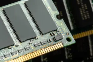
(fabrikasimf/Freepik)
What Are Microstrip and Stripline?
Microstrip
A microstrip routes signals on the external layer of a PCB. The signal trace sits on top of a dielectric substrate with a ground plane underneath. This creates a mixed dielectric environment where the signal interacts with both the substrate material and air, affecting propagation characteristics.
Microstrips excel in RF and microwave applications, including wireless communication devices, antennas, and general-purpose electronics. Engineers prefer them when they need external trace accessibility for testing and modifications.
Air surrounds one side of microstrips, making them more vulnerable to electromagnetic interference (EMI). However, they simplify fabrication and allow easier inspection than internal routing methods.
Stripline
A stripline places the signal trace inside the PCB between two dielectric layers with ground planes on both sides. The signal runs in a uniform dielectric environment without air contact. This design blocks electromagnetic interference and maintains consistent impedance control.
Designers typically use stripline routing in multi-layer PCB designs for high-speed digital circuits, aerospace applications, and EMI-sensitive environments. The consistent dielectric environment provides more stable impedance than microstrip, making it ideal for applications requiring precise signal integrity.
While engineers value stripline’s performance advantages, implementing this technology complicates manufacturing and increases costs due to additional PCB layers and stricter material requirements.
Key Differences Between Microstrip and Stripline
Microstrip and stripline configurations differ in several key areas, including signal propagation, impedance control, EMI shielding, and fabrication complexity. Here’s a closer look at their differences.
1. Placement and Structure
Microstrip traces run on the outer surface layers of a PCB, while stripline traces run inside the PCB between other layers. The placement directly affects how signals behave and how easily manufacturers can produce the board.
Microstrip designs allow a PCBA contract manufacturer to see, test, and modify traces without disassembling the board. Such visibility makes microstrip the better choice for simple one- or two-layer PCBs and for prototypes that require frequent adjustments.
Stripline designs position signal traces between internal PCB layers with ground planes above and below. The internal placement prevents direct access to traces after manufacturing. Any design changes require new board fabrication rather than simple rework, increasing both production time and cost.
2. Dielectric and Impedance Control
When designing high-frequency PCBs, controlling impedance prevents signal reflections that degrade circuit performance.
Microstrip traces interact with both PCB substrate and air, creating challenges for impedance control. PCB assembly manufacturers must carefully calculate trace width and thickness to maintain consistent signal performance.
Stripline traces operate within a single, consistent dielectric material. This uniformity allows for precise impedance control, making stripline the go-to choice for PCBA contract manufacturers handling projects where signal stability matters most.
3. Signal Integrity and EMI Shielding
Interference wrecks signal quality in high-frequency PCBs. On outer layers, microstrip traces remain vulnerable to EMI—they absorb noise from nearby components and external sources like a sponge. Without proper shielding, your critical signals degrade quickly.
Stripline traces enjoy natural protection. The two surrounding ground planes create an electromagnetic barrier that blocks outside interference. For multi-layer PCBs where clean signals matter, this built-in shielding eliminates crosstalk problems. High-speed data and RF applications also benefit tremendously from this protective environment, which explains why professional PCB assembly services recommend stripline for noise-sensitive designs.
4. Manufacturing Complexity and Cost Considerations
Budget-conscious engineers often choose microstrip for their electronic manufacturing services projects. Why? Fabricators create microstrip traces in fewer steps without adding extra layers. The simplicity translates directly to lower manufacturing costs and faster turnaround times—a significant advantage for prototype development.
Stripline fabrication demands precision at every step. Manufacturers must perfectly align multiple layers, carefully control material properties, and use sophisticated techniques to embed traces within the PCB. These requirements drive up production costs considerably. Despite the expense, engineers accept these trade-offs when signal integrity outweighs budget concerns in their electronic manufacturing projects.
Selecting the Right Transmission Line for Your PCB Design
Your choice between microstrip and stripline will depend on signal frequency, design complexity, EMI requirements, and budget constraints. Consider these guidelines when planning your next PCB assembly project:
Choose Microstrip When:
- You need cost-effective PCB fabrication with fewer layers
- Your signals run at lower to mid-range frequencies where EMI concerns remain minimal
- Your design requires easy access for testing and modifications during development
Choose Stripline When:
- Your design features high-speed signals that demand precise impedance control
- Your application requires strong EMI shielding to block interference from external sources
- You’ve already planned a multi-layer PCB layout, making internal signal routing practical
Evaluate your specific requirements carefully to select the transmission line structure that delivers optimal performance and manufacturability for your electronic manufacturing project.
Conclusion
Microstrip and stripline affect your PCB’s performance, cost, and manufacturing complexity in fundamentally different ways.
Microstrip saves money by requiring fewer layers and simpler manufacturing. Your team can easily test and modify these surface traces during development. However, external traces attract interference and exhibit variable impedance that can compromise signal quality in sensitive applications.
Stripline surrounds critical signals with protective ground planes. This shielding blocks interference and maintains consistent impedance—crucial for high-speed data transmission. The downside includes more complex manufacturing steps and higher production costs due to additional layers.
For budget-conscious projects with moderate performance requirements, microstrip delivers the best value. For high-speed, noise-sensitive applications where signal integrity matters most, stripline justifies its higher cost.
