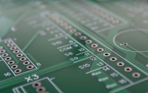
Printed Circuit Board drilling is an intricate process that requires a high level of expertise to prevent loss. Even the smallest error can result in significant damages, which is why it’s crucial to get this part of PCB manufacturing right.
A PCB requires holes according to specific requirements. Some of these holes help to mount components, while others connect different layers of the board. Each of these holes is drilled on the board, and it is an irreversible process. An in-depth look at hole types, drilling equipment, and drilling processes will help you understand the manufacturing process of a PCB.

(LogitroniX / pixabay)
Types of Drill Holes in PCB
Drill holes in printed circuit boards can be classified based on their current carrying tendency. However, this categorization does not cover the importance of drill holes in a circuit board’s structure. The better way to classify drill holes is according to their use in a PCB. Let’s look at the types below:
Non-Plated Through Holes
Fasteners. Fasteners ensure that any installed component that requires additional support is installed correctly. The main role of fasteners is mechanical justification.
Mounting Holes. These holes are intended for mechanical fasteners in installations where the vertical clearance is not the concern.
Countersink Holes. These holes are used for mounting boards in which you lower the bolt head below the surface.
Plated Through Holes
Press Fit. These holes do not require solder or fill as they fit the leads of through-hole pcb components.
Blind Vias. Blind via holes provide a connection between a surface and the internal layer of the stack up. Unlike through-hole vias, the blind vias only apply to targeted layers.
Buried Vias. Buried vias are connections between the internal layers that don’t extend to the top or the bottom surfaces.
Micro Vias. Micro vias are different from other vias due to their size. They are used in high-density signal routing and may be blind or buried.
Thermal Vias. Thermal vias do not conduct current; however, they leverage the high transfer rate of copper to remove excess heat, usually from a high-power component from the board’s surface.
PCB Drilling Equipment
Drilling in a circuit board is a common procedure, but it is also a delicate process requiring special equipment. While many types of numerically controlled (NC) machines are used for drilling, the larger production ones can drill around 30,000 holes every hour with a speed of up to 110,000 RPM. Overall, there are three types of machines used in the drilling process:
- Automated drill
- Mill machine
- Laser drill
Most component companies make PCBs with the help of an automated drilling machine, but these machines also vary according to their specifications.
Mill machines are useful due to their varying flexibility, which helps shape the board and perform various drilling operations. For smaller holes like micro vias, a laser drill is the best choice.
Considerations for the Proper Drill Selection
Apart from the basic requirements of drilling in a PCB, layout engineers can help with the board design in the following ways:
Same drill diameter
If the board has many holes on it with different diameters, it may require a change of drill bits in the middle of the drilling process. These changes can give way to tolerance errors between the holes and their size. Therefore, you should standardize the drill hole size requirements.
Minimum drill diameter
For boards that are 62 mils thick, the mechanical drill size should be 6 mils or bigger. Small drill sizes are harder to drill mechanically, and the aspect ratio makes them even harder to plate. This issue will require the use of the expensive laser drilling process, so for boards larger than 62 mils, you’ll need to invest in a larger-sized drill.
Using blind and buried vias
Do not use blind and buried vias if they are not a requirement for high-density designs. The buildup process for blind and buried vias makes the board much more expensive.
PCB Drilling Tips & Tricks
Since drilling requires precision and accuracy, here are some tips and tricks to help you make the process foolproof:
- The step before drilling an actual hole is to drill a pilot hole. It will disable the drill from ‘walking’ and slipping into other components while drilling.
- Use a straight drill bit even when drilling at an angle for accuracy. The sizes of the drill bit are to be determined by the designer.
- Use the correct size of a drill bit to avoid damaging the circuit board.
- Use a drill bit with the right speed and power to go through the material
- A drill press is your best bet for drilling accurately. These presses are four times more efficient in making the right size of holes.
- Clean the PCB after drilling a hole with a brush and a solvent to avoid the buildup of metal shavings. It will lead to a smoother and finer drilling process.
- Once done with drilling, apply solder to the new holes and use a soldering iron to melt them. This will firmly attach and make the solder neat around the holes.
There are so many aspects of drilling a PCB that directly affect the cost of manufacture. Each aspect leads to a different version of the PCB if not controlled in the design phase. The size of the drill holes alone has a huge impact on the performance of the PCB. If the holes need to be small, the cost of the board will jump high. And in the case of larger holes, the PCB assembly process becomes difficult and expensive.
If you need help with drilling concerns, talk to our expert USA-based electronic manufacturing service providers. The drilling process alone is a huge expense, and any little mistake can add up to unforeseen costs. On the other hand, precision drilling can make PCBs cost-effective and efficient.
Video

