As technology advances, the need for efficient production techniques in PCB design has become more crucial. One component of PCBs that requires more attention is the guard ring.
While some may view the guard ring as less critical than resistors or batteries, it still plays an essential role in protecting the circuit board from electromagnetic interference. However, many designers don’t understand its significance or how to use it correctly.
In this guide, we will explore what PCB guard rings are and how they work with other components.

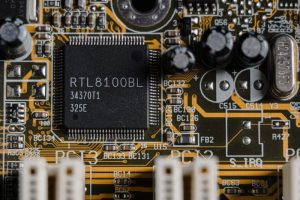
(Tima Miroshnichenko/Pexels)
What is a PCB guard ring?
A PCB guard ring is an important component used in printed circuit boards to prevent the loss of voltage or current to other conductors near the circuit. Its purpose is to surround the surface current with a potential problem or where there is a leakage, especially in AC circuits.
The guard ring is a thin copper wire connected to a low-impedance voltage source to ensure that the circuit remains closed and that no voltage or current escapes. By ensuring that the current in the guard ring is equal to the current within the circuit, the potential difference is rendered zero, preventing any leakage.
Despite being a seemingly simple component, PCB guard rings play a critical role in maintaining the stability and integrity of the circuit. They are essential for ensuring the efficient and stable operation of the circuit by preventing signal loss and reducing interference.
Why use guard rings?
As the complexity of the printed circuit board assembly (PCBA) continues to grow, multiple signal types, including AC, propagate along surface traces and through vias. Precision is paramount for certain applications where highly accurate readings are necessary to prevent misdiagnosis.
Low voltage components typically do not require common shielding that encloses the component to mitigate electromagnetic interference (EMI). However, small variations in current due to leakage can significantly impact the output and readings.
Guard ring vs. guard trace
In PCB design, there are multiple shielding methods to protect sensitive traces and nodes from electromagnetic interference and stray currents. The guard trace is one such method that differs from the guard ring. While the guard ring circles a node, the guard trace is a copper conductor placed in parallel between two copper traces.
The guard trace aims to shield a sensitive trace from a high-speed signal that may cause electromagnetic interference. On the other hand, the guard ring protects a node against stray currents. Knowing the difference between these two methods is crucial for choosing the right one for your specific PCB design needs.
How to design effective PCB guard rings
In designing effective PCB guard rings, there are several factors to consider to ensure optimal performance. First, the input node(s) should be encircled by the ring since they are typically the high impedance node being protected. Additionally, the ring should be connected to the appropriate nodes, depending on the potential polarity choice.
Another crucial consideration is to minimize the thermocouple effect, which typically generates a high current that impacts precision in low-voltage circuitry. Avoiding crossing other metal types with the ring can help prevent this issue.
Moreover, since the EMI from nearby traces and conductive elements may affect the guard ring, it is critical to observe adequate clearance and creepage guidelines. By doing so, you can ensure that the guard ring operates optimally and provides the necessary protection for your circuitry.
PCB guard ring and EMI
In PCB design, EMI can cause significant disturbances that can result in circuit malfunction or inaccurate results. Despite the varying levels of interference each component can create, no EMI should be neglected, as even the smallest amount can cause issues.
To counteract this issue, designers must consider all components and their interference levels, which can range from 50 kHz to 50 MHz. Crosstalk, a common issue in circuits, can produce high levels of EMI, making it essential to reduce the interference as much as possible.
One effective method for reducing EMI is through guard traces, which work by shielding off sensitive traces against high-speed signals that may cause electromagnetic interference. By eliminating crosstalk, guard traces can substantially reduce the EMI created by crosstalk and improve the overall performance of the circuit.
Therefore, it is crucial to properly combat EMI and implement guard traces, as even the smallest amount of interference can impact the function of a printed circuit board.
A PCB guard ring plays a crucial role in ensuring the optimal functioning of a low-voltage circuit. Its ability to minimize current leakage is highly valuable, especially when measuring small units of current or voltage. By enclosing the inputs of a circuit with copper wires, the guard ring eliminates the risk of current leakage by equalizing the voltage within the cables.
However, the effectiveness of guard rings heavily depends on their placement on the printed circuit board. It is crucial to work with a competent PCBA manufacturer who can create boards that are designed to accommodate the guard ring placement. Because, at the end of the day, attention to every detail will determine the success of a circuit design.
Infographic
In today’s tech-centric world, PCB efficiency is vital, and guard rings are essential in protecting against electromagnetic interference. These simple copper wires encircle circuits, preventing voltage issues, especially in AC systems. In complex PCB designs, guard traces and rings shield against interference and stray currents, requiring precise design considerations and manufacturer collaboration for optimal performance.

Video

