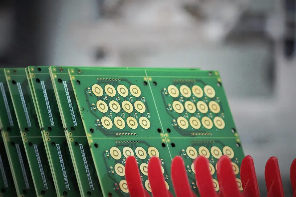
Printed circuit boards are found in almost every electronic product on the market. Improvement in technology has allowed designers to push the limits for PCBs, making them smaller and thinner and able to be produced in massive quantities.

(Pixabay / ranjatm)
Since PCBs are manufactured in bulk, any fault that is found in one PCB may also be present in hundreds or thousands of PCBs that were produced in the same batch. Buyers of PCBs expect that the manufacturer has incorporated a certain level of quality into their products.
So how exactly do PCB manufacturers ensure that their PCBs are up to snuff? They employ quality assurance checks and validate each assembly with their own inspections. Here are just a few methods for checking PCBs:
Visual check
Visual inspection can be an effective tool for smaller production runs. The inspector will simply look at the PCB samples with his or her own eyes, meticulously checking each connection in the PCB.
Microscopic or x-ray inspection
These inspections are more thorough than the visual version. A microscope allows the inspector to view the PCB in an enlarged format. This gives insight into fine details that can’t be seen with the naked eye. Inspectors use USB microscopes that project the image onto a large screen for their highly detailed inspections.
X-ray inspection is another option here and a non-invasive way of inspecting the components of the PCB assembly. An X-ray allows an in-depth examination of the PCB components that will not be possible with a visual inspection.
Capacitance tests
The in-circuit test is a type of capacitance testing where electrical probe tests are conducted on a PCB. The purpose of this test is to check for shorts or resistance. The in-circuit test may be performed on a bed of nails type of test fixture using special test equipment, or with a fixtureless in-circuit test setup.
Cross-section inspection
This type of inspection sacrifices a PCB unit in order to provide insight into the overall assembly process. Using a saw that slices through a PCB, resulting in a sample cross-section, a test is conducted on the inner parts of the PCB to see how the components are connected. You have to weigh the costs and benefits of this test method. Yes, you lose a PCB here, but you get a very insightful look at the inner workings of the product.
Automated Optical Inspection
This quality inspection method involves the use of webcams attached to Open Source Computer Vision that makes a comparison of the PCB images to those of a perfect sample. In the process, AOI identifies incongruences or defects. Automated Optical Inspection can make use of either cheap grade or commercial grade camera systems.
Trial run
You can assess the quality of a PCB by allowing it to do what it’s supposed to do. Quality assurance inspectors power up the product and run it through a series of tests to ensure that it is performing according to its intended function.
At EMS, we offer four SMT lines supported by state-of-the-art Automated Optical Inspection equipment. This ensures a top-of-the-line product every time. In addition, we offer turnkey solutions to help companies develop their own advanced test solutions for their products.
