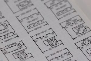
Schematics are detailed electrical diagrams defining the connections, wirings, and relative placements of each component. A quick glance at a schematic can reveal the complete inner workings of the whole circuit, serving as a roadmap for troubleshooting or building a circuit, whether as a DIY project or a graded university project.
It’s fairly easy to understand circuit schematics, and it’s an extremely valuable skill to have for hobbyists and professional engineers. All it takes is some basic familiarity with symbols representing components and visualizing how you can practically replicate the wiring connections displayed in a schematic.

(777546 / pixabay)
Let’s delve into the basics of reading schematics and take the first steps to build and troubleshoot your circuits.
Fundamental Schematic Symbols
In the world of electronics, there are a few elements that almost every circuit consists of. You’ll quickly get familiar with these because of how frequently they appear in circuitry:
Power Sources
Every circuit needs power to function, so power sources are universal circuit elements. The most readily available power source is a simple battery, which looks like a pair of parallel lines (one shorter than the other) in a schematic. The longer line represents the battery’s positive terminal, while the shorter line is the negative terminal.
The battery voltage is labeled next to its symbol, and for small circuits, it is usually 5 Volts or 9 Volts.
Another popular symbol for voltage sources commonly found in circuit analysis textbooks and simulation software consists of a small circle with “+” and “-” labels next to each terminal. This is the symbol of a constant DC (direct current) voltage source. For AC (alternative current) voltage sources, the symbol is a circle with a sine wave inside. Since AC is a waveform, the label will mark the voltage value as well as the frequency that the AC power source is generating.
Basic Passive Components
Passive components are cheap, easy to work with, and can be used to produce dozens of interesting circuits. Typically, passive components are two-terminal elements that cannot amplify power in the circuit. They can only store or dissipate power in the form of heat, light, and electricity.
Let’s look at the symbols for some of the most common passive electrical components:
• Resistors
A resistor is probably the most widely recognized symbol in a schematic. Thanks to its simple, linear behavior, resistors are the easiest components to analyze and greatly help beginners understand basic circuit theory.
The symbol for a resistor, a few zig-zag lines that flatten out to two terminals on each side, is accompanied by a resistance value in Ohms. An alternative symbol simply consists of a narrow rectangle with two terminals on either side.
• Potentiometers and Variable Resistors
The standard resistor has a fixed Ohm value. However, for applications where you might need to change the resistance value in a certain segment of the circuit, you can make your job much more convenient using a variable resistor.
The symbol for a variable resistor is simply the standard resistor, with the addition of an arrow crossing the wiggly resistor line across the middle. A potentiometer is a three-terminal device, so the symbol features an arrow perpendicular to the zig-zag, representing the third terminal.
• Capacitors
A capacitor stores electrical energy and displays quite interesting behavior when used in an AC application. If you’ve ever encountered a capacitor in a schematic, you might have noticed that there are two different capacitor symbols.
One symbol represents a non-polarized capacitor. When you have a non-polarized capacitor, the terminals are interchangeable, i.e., it doesn’t matter which side is connected to a particular wire/component. The symbol for a non-polarized capacitor is simply two parallel lines of equal length.
A polarized capacitor symbol has one straight line and one curved line. The curved line represents the negative terminal (cathode), while the straight line represents the anode (positive terminal). The polarized capacitor must be connected with the correct polarity as defined in the circuit if you don’t want to risk damage.
• Inductors
The symbol for an inductor (which stores magnetic energy) consists of a series of loops that extends into two terminals on either side. Unlike a capacitor, inductors are always non-polarized and can be connected in any alignment without the risk of malfunction.
An alternative symbol for inductors is a solid, narrow rectangle similar to that of a resistor. The difference is that the inductor rectangle is larger in size and solid, unlike the smaller, hollow rectangle of a resistor.
Active Component Symbols
Active components are usually semiconductor-based. Unlike passive components, active components like transistors can amplify power in a circuit.
Some of the most common active components and their associated schematic symbols are:
• Diodes
The standard diode symbol is a small triangle with a vertical line touching the flat edge of the triangle. This end marks the negative terminal of the diode, while the other end is positive.
Unlike a capacitor, a diode won’t explode if you reverse polarities in the circuit. Still, it won’t behave in the desired manner if you go against the polarities defined in the schematic. There are various types of diodes such as Zener diode, LED, photodiode, etc., each having its own symbols besides the standard ones.
• Transistors
Transistors are three-terminal components and come in a variety of types. The most popular are BJT (Bipolar junction transistor) and MOSFET (Metal Oxide Field-Effect Transistor). These transistors can be further subdivided into two categories based on configuration: p-channel and n-channel for MOSFET; NPN and PNP for BJTs.
The three terminals of a BJT are labeled: collector (C), emitter (E), and base (B). In MOSFETs, these are labeled source (S), drain (D), and gate (G). It’s important to make sure that your terminals are correctly positioned, as shown in a schematic. A transistor’s function changes drastically with a simple change in terminal configuration.
• Integrated Circuits (ICs)
Unlike discrete components, integrated circuits have no standard symbol. Each IC performs unique functions, comes in a wide range of sizes, number of pins, etc. The only common aspect of an IC symbol is a rectangular box with pins protruding on both sides. These pins are labeled with a number and a function.
Understanding Connections
Once you’re reasonably familiar with the components that schematic symbols represent, turn your attention towards wirings and connections between components. In larger schematics, it can be particularly confusing to understand the correct placement and connections.
Much of this confusion goes away with practice and the realization that two points in a schematic might be geometrically separate but electrically common. Wires in schematics can run over each other without being connected. A dot in the schematic symbolizes a node or junction where several wires join together.
Careful attention to these details can eliminate most errors when replicating a circuit design in practice while enabling you to draft your own schematics for university, home, or workplace projects.
Wrapping Up
Reading schematics can seem daunting initially, but it gets easier the more schematics you come across and use to build circuits. Although it is an elementary-level skill for PCBA manufacturers and assemblers, they continue to rely on schematics throughout their careers for troubleshooting, modifying, and building new circuits. If you’re just starting out, make sure to focus and pay attention to every detail in a schematic. This habit will turn you into a proficient analyst of schematics.
Video

